
The fiber part of the fiber optic telecommunications system is made up of lengths of optical fiber that must be connected to each other to provide pathways for the optical signals to get from where they start to where you want them to go. Although the connections with the least loss of the signal are permanent fusion splices (in which the ends of two glass fibers are melted together), there are many situations in which you do not want a permanent connection. For example, you might want to connect a television camera to one TV set at one time and another TV set at another time. It would be very inconvenient to have a permanent connection that you could not change without physically breaking the connection to one set and installing another permanent connection to the other. When you want to have a connection that can be changed conveniently, you use fiber optic connectors.
Common Connector Types
There are quite a few types of connectors on the market at this time. You might still find SMA connectors on older equipment. They come in two styles (called 905 and 906), but are very rarely used nowadays. Current single fiber connectors include FC (sometimes called FCPC), SC, and ST types. One type of dual fiber connector is specified in the FDDI (Fiber Distributed Data Interface) documents. Each of these connector types must meet very tight specifications. There are many other connector types, but these are among the most common.
What Makes a Connector Good?
To be useful, a connector has to have certain properties. Among them are the following:
1. A connector has to allow as much light to get through as possible.
2. A connector has to be rugged.
3. A connector should allow the same amount of light through each time it is disconnected and reconnected.
4. A connector should be easy and simple to install.
5. A connector should be inexpensive.
It is not easy to meet these requirements. For example, the better the quality of the connector, the more likely it is that it will be expensive. People who design connectors must make compromises to get the best combination of properties for the least money.
Our experiment.
We are going to install a pair of ST connectors onto a length of jacketed fiber optic cable. We will use cable that is 3mm in outside diameter. We will use several different tools to remove the various protective layers that surround the fiber in the cable. We will then attach the connector ends, polish the fiber, and test the completed connectorized cable. The connectorization and polishing will take several sessions. Testing the cable will take another.
It is very important to WORK CLEAN if you wish to succeed in preparing a fiber optic cable and installing connectors on each end. A clean work area is less confusing and much SAFER. Please dispose of all fiber scraps as well as all pieces of cable jacket, buffer material and Kevlar as soon as possible.
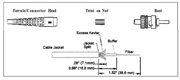
1 Slide the boot and Kevlar retention nut onto the cable as shown. (Figure 1a) The nonthreaded end of the nut must face the boot.
2 For jacketed cable, strip the outer jacket using the Template (Figure 1) as a guide and use the jacket stripping tool. (This has a red handle and a wire cutter. Use the 1.3mm cavity.) Use the same tool with the .4 mm cavity to remove the white tubing. On the template, the section marked “Buffer” is the white tubing.
3 Using the buffer stripping tool (No NIK), precisely strip the buffered fiber to the length on the Template. Use a brush to remove debris from the tool. A clogged tool may break the fiber. Leave the yellow Kevlar strands as shown.
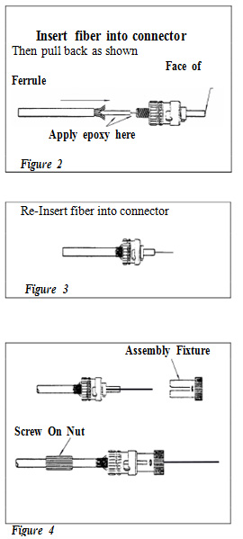
4 Slowly insert the fiber into the connector until it comes out of the other end. A slight rotation of the connector will help. (Figure 2)
5 Pull the fiber back out.
6 Slide the protection sleeve over the ferrule.
7 Carefully inject the epoxy into the back of the connector until it appears on the face of the ferrule. Apply a drop of epoxy to the threads of the connector before screwing on the rear nut. Reinsert the fiber into the connector. (Figure 3)
8 Insert the connector into the plastic assembly fixture (which may be red or black) and holding it firmly screw the rear nut onto the connector, capturing the Kevlar strength members in the threads. Remove the assembly fixture. Be careful not to break the fiber. (Figure 4)
NOTE: Clean any epoxy from the side of the ferrule with lint free tissue and alcohol. Wash epoxy from your hands, immediately.
9 Put the connector with the protective sleeve into one of the oven holes for 5 minutes at 100 o . Let it cool; then remove the protection sleeve.
10 Holding the cleaving tool (in plastic tube) with the trigger upwards, slowly insert the ferrule with its protruding fiber into the slot of the cleaving tool. Insert the connector until the ferrule end face stops against the stop screw.(Figure 5) Release the connector and gently press the trigger to cleave the fiber. Remove the connector from the tool. Safely dispose of excess cleaved fiber
11 Insert the connector into the polishing tool. Using the glass plate mount a sheet of BLACK lapping film. Put a few drops of water on the film. Perform 10 figure “8” motions over the entire length of the
lapping film. (Figure 6) Virtually no pressure should be applied to the tool at the beginning of this step.
Gently clean the contact with a lintfree tissue and alcohol between each polishing step.
12 Mount a sheet of GREEN lapping film and perform at least 15 to 20 figure “8” motions over the entire length of the lapping film.
13 Slide the boot up until it fits securely over the rear nut.
14 Remove the connector from the polishing tool and carefully clean the ferrule with lintfree tissue and alcohol. Make sure that it is dry. Use the Video Fiber Microscope (or a 100X microscope) to inspect the quality of the polish. No scratches or cracks should be visible. (Figure 7)
NOTE: DO NOT put a wet connector into the Video Fiber Microscope.
NOTE: If you use a 100X microscope, store it in a closed position when not in use. This will insure longer battery life.