
Reflectance and dead zone
OTDR, short for optical time-domain reflectometer, is an opto-electronic equipment used to characterize fiber optic link. OTDR reflectance and dead zone is the two key factors. This white article is for explain it, and help operators, engineers, service providers etc. know the importance of it and how to choose the right pulse width during optical cable testing, to reducing dead zones, and increase measurement accuracy for the fault locations.
Pulse widths and Reflectance
The attenuation dead zone found on the trace of an OTDR is normally thought to be dependent upon one main factor: The length of the pulse (pulsewidth) of light sent down the fiber. With each pulse width that is selected, there is a corresponding pulse width-related attenuation dead zone. The longer the pulse in seconds, the wider the attenuation dead zone in meters.
However, once the preferred pulse width for viewing the fiber is established, other factors become apparent. With one selected pulse width, there may be a varying attenuation dead zone for reflective events – varying with the distance that the event is located from the OTDR and with the intensity (amplitude) of the reflective event.
The detector in the OTDR minutely measures the levelsof returned light. Normally, the return levels are of very low intensity and recorded by an extremely sensitive detector. However, when the light strikes a highly reflective connector, the level of returned light may jump almost instantaneously.
Factors That Affect Amplitude
The factors that determine the level (amplitude) of this returned light are:
• The distance from the OTDR to the event. Thisis due to its attenuating affect on the amplitude of light returning to the OTDR. The further outthe event, the more attenuated the amplitude of light that returns to strike the OTDR’s detector.
• The reflectance of the event. The greater the reflectance of the event, the greater the amplitude of returned light. If the event is very reflective and close, it may increase the attenuation dead zone. If the event is less reflective and farther away, it may or may not increase the attenuation dead zone.
Receiver Saturation
The reason that attenuation dead zone increases without an increase in pulse width is due to receiver saturation. The longer the pulse width, the longer the saturation of the detector in the OTDR’s receiver.
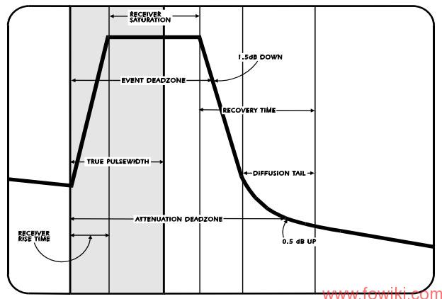
The follwoing figure shows the characteristics of a Fresnel reflection. As the actual pulse width increases, so does the receiver saturation and, hence, the attenuation dead zone. It is still possible to change the attenuation dead zone of an event – without changingthe pulse width – through the amplitude rather than the pulse width of returned light.
Increased amplitude of the returned light will drive the OTDR’s detector harder, increasing the level of saturation, thereby lengthening the time it takes for the detector to recover. The longer it takes for the detector to recover, no matter what the cause, the longer the attenuation dead zone.
Fresnel equations describe the behavior of light when moving between media of differing refractive indices. The reflection of light that these equations predict is known as Fresnel reflection.
Conclusion
This paper helps a spectrum of field technicians to choose the appropriate pulse width on any OTDRs, by reducing dead zones and improving the accuracy of fault locations. It can be summed up as follows: Once the pulse width is selected and locked in, the amplitude of returned light can change the attenuation dead zone. Anything that affects this amplitude, the level of the reflective event and its distance from the OTDR, can also affect the attenuation dead zone.