
Attenuation is the reduction or loss of optical power as light travels through an optical fiber. The longer the fiber is and the farther the light has to travel, the more the optical signal is attenuated. Consequently, attenuation is measured and reported in decibels per kilometer (dB/km), also known as the attenuation coefficient or attenuation rate. Attenuation varies depending on the fiber type and the operating wavelength (see Figure 1). For silica-based optical fibers, single-mode fibers have lower attenuation than multimode fibers. And generally speaking, the higher (or longer) the wavelength, the lower the attenuation. This is true over the typical 800 – 1600 nm operating wavelength range for conventional datacom and telecom optical fibers.
Single-mode fibers usually operate in the 1310 nm or 1550 nm regions, where attenuation is lowest. This makes single-mode fibers the best choice for long distance communications. Multimode fibers operate primarily at 850 nm and sometimes at 1300 nm. Multimode fibers are designed for short distance use; the higher attenuation at 850 nm is offset by the use of more affordable optical sources (the lower the wavelength, the less expensive the optics).
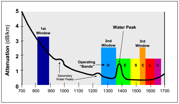
Fig. 1 Attenuation spectrum of optical fiber
Attenuation Causes of Optical Loss
Fiber attenuation is caused by scattering, absorption and bending. Scattering (often referred to as Rayleigh scattering) is the reflection of small amounts of light in all directions as it travels down the fiber. Some of this light escapes out of the core, while some travels back toward the source (this backscattered light is what an Optical Time Domain Reflectometer, or OTDR, “sees”). Some scattering is caused by miniscule variations in the composition and density of the optical glass material itself; this represents the theoretical lower limit of attenuation.
Additional variations in density and concentration – and therefore, more scattering – are caused by the dopants used in the core glass to change the refractive index of different types of fiber. Fibers with increased dopant concentration exhibit more scattering and greater attenuation than fibers with less dopant in the core. That is why multimode fibers, with their higher level of dopant in the core, have higher attenuation than single-mode fibers. Absorption occurs when impurities, such as metal particles or moisture, are trapped in the glass.
These cause attenuation at specific wavelengths by absorbing the light at that wavelength and dissipating it in the form of heat energy. Attenuation due to metals is not an issue with OFS fiber, since we use ultra-pure glass and dopant chemicals, and our highly advanced manufacturing techniques introduce no traces of metal into the fiber. Moisture occurs more naturally in fiber, and accounts for the rise in attenuation at the “water peak” found near 1385 nm. This is why fibers were traditionally not used in this wavelength region. OFS has patented processes to create a “zero water peak” fiber that permanently eliminates moisture in the fiber. Today, OFS’ AllWave® ZWP single-mode fiber operates efficiently across a broad spectrum of wavelengths, including the water peak region, providing 50 percent more bandwidth when using coarse wavelength division multiplexing (CWDM) systems.
Bending occurs in two forms – microbending and macrobending. Microbends are microscopic distortions along the length of a fiber, typically caused by pinching or squeezing the fiber. Microbends deform the fiber’s core slightly, causing light to escape at these deflections. In single-mode fiber, microbending is wavelength-dependant, with microbend sensitivity increasing as you move to higher wavelengths like 1550 nm, and especially 1625 nm. In multimode fiber, microbend sensitivity is relatively constant across the wavelength spectrum. 50 µm multimode fiber is more microbend-sensitive than is 62.5 µm fiber, due to its smaller core diameter and smaller Numerical Aperture (NA). Macrobending occurs when a fiber is bent in a tight radius. The bend curvature creates an angle that is too sharp for the light to be reflected back into the core, and some of it escapes through the fiber cladding, causing attenuation. This optical power loss increases rapidly as the radius is decreased to an inch or less. Fibers with a high numerical aperture and low core/clad ratio are least susceptible to macrobend losses.
Understanding Fiber Optics Measuring Attenuation
Standards for measuring single-mode and multimode fiber have been established by the Telecommunications Industry Association (TIA) and adopted by the American National Standards Institute (ANSI). Equivalent standards are published internationally by the International Electrotechnical Commission (IEC). At OFS, we measure the attenuation of every spool of fiber using a standard cutback technique specified under Fiber Optic Test Procedure (FOTP) 78 (IEC 60793-1-40).
FOTP 78 also specifies the control of launch conditions in accordance with FOTP 50. By following the standardized procedure, OFS is assured of achieving accurate, repeatable measurements. TIA and IEC also recognize that attenuation can be measured with an OTDR, also as specified in FOTP 78. This technique is frequently used to measure attenuation in the field. Attenuation values should be relatively consistent between both measurement techniques.